- DME Channel on YouTube
- Video in higher resolution
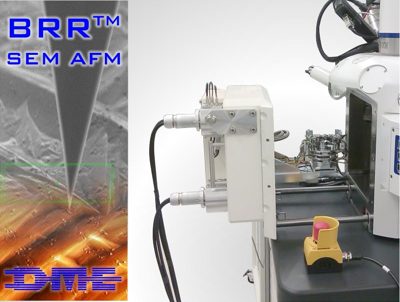
The BRR is an unification of a scanning electron microscope and an atomic force microscope.
It unites the best properties of both worlds without making performance compromises for both components.
In addition, the new system has more advantages than the single systems.
This system built by DME is a SEM-AFM Integration for Zeiss GeminiSEM and Crossbeam. A retrofitting of existing systems is also possible at any time.
- Is based on the DME UHV AFM and the Carl Zeiss AURIGA® Crossbeam Workstation.
- The crossbeam point of SEM and FIB lies at the cantilever tip. The design as a sample scanner allows combination measurements of all three techniques at exactly the same point in space and on the sample.
- Extremely stable scan unit designed for three dimensional single atomic resolution
- Scanner Specification: Scan range (x,y,z) 10 µm x 10 µm x 1 µm, real resolution subatomic in all three dimensions
- Single software interface for both SEM and AFM components
- Common data storage of AFM and SEM images
- SEM viewing angle from 0° to 85° while keeping minimum SEM working distance of 5 mm
- Cantilever tip and sample can be reached by FIB in 0° and 54° position, in-situ tip sharpening by FIB supported
- Supports easy change between AFM and standard Auriga® functionality by user exchangable SEM door
- Unlimited functionality by using all standard AFM cantilevers, no active probes required
- Supports all common AFM operation modes
- Automatic laser / detector alignment on cantilever change
- Update of existing Auriga® SEMs to BRR functionality possible by simple door exchange
- More information you find in our datasheet (pdf)
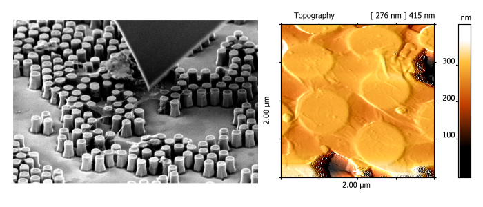
- The world seen by SEM-AFM: Applications
Why build a combined SEM-AFM?
A combined SEM-AFM has a number of advantages in comparison to the two systems as stand alone.
The system offers new possibilities for measuring surfaces and nano structures. The combination
of SEM and AFM offers an exact positioning of the AFM tip. The AFM gives you precise information
about topography, electrical and mechanical properties of the surface.
Some more measurements you can watch in our videos and applications.
You can read more advantages of the combined system in our article SEM and AFM – high resolution with overview.
Our approach to realize a combined SEM-SPM system is based on the integration of a vacuum compatible SPM into existing SEM systems. This combination was selected to reach the highest performance and usability of the system. Another benefit of this strategy is that existing SEM systems can be upgraded to a combined SEM-SPM system. In both cases, the SEM will be not limited in its function so that combined SEM/SPM measurements are possible.
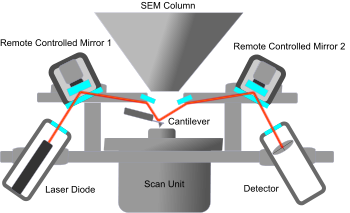
- Laser path
The SPM for integration is designed as a sample scanner. This design enables alignment the electron beam and the SPM tip with the highest precision, because the beam and tip are not moved against each other. Even during SPM scanning, this enables unknown possibilities of combined measurements. Additionally, highest performance in terms of resolution and frame rate can be achieved by this setup. The scan unit itself is the next developmental step of our STM scanner, known for high stability and reliance in the last decades. With a scan volume of 9 µm x 9 µm x 1 µm and a possible sample size of 10 mm, the design claim for high resolution is clearly visible. Electronic components like the laser diode, the detector, and preamplifier are located inside the vacuum chamber in hermetically encapsulated compartments. The alignment of the laser path and also the exchange of the cantilever and the sample can be performed without breaking the vacuum. The positioning of the SPM in respect to the SEM and positioning the SPM tip to the area of interest can be realized by remote control. With a small number of changes to the SPM, a UHV compatible version is available.
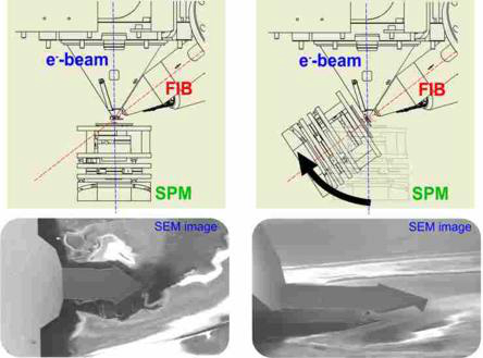
The system is realized as an integration of the DME developed SPM into a ZEISS AURIGA System. In this system, SEM, FIB, and SPM will be united and can be performed in combined measurements. The SPM is mounted to a specially designed stage which enables vertical and rotational movement. This stage is part of the main door of the AFM (see figure on the left). In this setup, the SPM tip can be aligned with the FIB e-beam cross point and rotated around it in an angle of about 75°. This enables the operator to either align the e-beam or the FIB perpendicular to the sample surface. The rotation of the whole SPM opens the possibility of working with commercially available Si and SiN SPM probes, because it is possible to observe the tip with the SEM from a sidewards angle (see Fig on the right). With a free field of view for the SEM, the SPM tip can be positioned to the area of interest under total observation by SEM with nm precision. From a view position perpendicular to the sample, the view on SPM tip is blocked by the cantilever itself. The SPM the tip can be positioned to the area of interest under total observation by SEM.
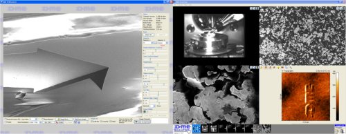
The grade of functionality of highly complex scientific instruments like the SEM-AFM, depends on the operating software. To achieve the seamless integration of the to methods, a single software user interface is a must. The open design of our SPM Software ScanTool™ enables us to integrate a self designed SEM operating software. So the operator is able to control both systems from one and the same software without clicking through a labyrinth of tabs and windows. The view on all settings and image data of both methods is unblocked and accessible. The software is designed for highest work flow and throughput. At the same time, program functions like the DME Automator gives access to all functions of the BRR™SEM-AFM system, so that user designed advanced measurement routines can be designed and performed. So it is possible to create automatically running measurement routines for the acquisition of comparable data from different regions of the sample. Image data from SEM and SPM are analyzed in the ScanTool™ software. Standard analyzing tools are available, more advanced or specialized analysis procedures can be selfimplemented or implemented by us on customer demand by the use of the "DME Automator" or "DME Image Calculator".