- DME Channel on YouTube
The AFM is an instrument that performs precision measurements of height variations on an atomic scale. But often the AFM images not only contain information certain details - they should also look good. In most cases, this requires some further processing. Below will be shown how simple processing tools may improve the looks of an AFM image without loss of the information in the image.
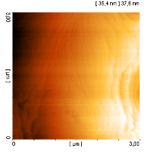
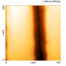
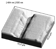
To the right is shown an unprocessed AFM image of a Gallium Nitride (GaN) surface. GaN is a semiconductor material, e.g. used for manufacture of blue and white LEDs. The image was recorded with a small DS 45-40 scanner in a cleanroom at the "Institut für Angewandte Physik" at TU Braunschweig. The scanner was mounted in the "Igloo" stage which stood on a normal metal table. As the scanner was not shielded, the permanent air flow of the cleanroom as well as operating pumps made a slight, low frequent noise signal which can be seen as horizontal lines in the image. Furthermore, the sample is sloping app. 0,4° in relation to the scan plane. Such a slope can hardly be avoided and will be seen especially with flat samples like the present.
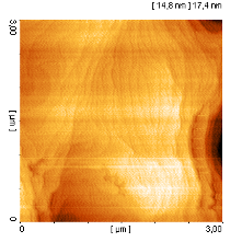
A clear improvement is obtained when one approximates the sample surface to a plane and deduct this plane from the data (slope correction). Hereby the slope disappears and the interesting structures can be seen more clearly. Now also the low frequent noise is enhanced. Luckily, this noise can be almost eliminated when one subtracts the mean value from each scan line (line mean function).
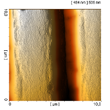
The image to the right is the result after slope correction and line mean. Now, one can see the atomic layers very clearly. The "basic noise" occurring within the atomic layers cannot be caused by ordinary GaN layers, since the noise is smaller than the distance between the atomic layers. It might be half layers or adsorbed atoms, but it is not possible from these images to distinguish between the two.
Line mean and slope correction are standard tools in Scanning Probe Microscopy. They are very often used, and most result in an enhanced image quality. Often the data are processed in this way, already during the scanning, so that it is possible to judge the quality of the result during the measurement. By the way, DME's scan software always records the un-manipulated data, so after using certain image processing tools, you can go back to the original. From the images shown here, you can see that also on a normal table under far from ideal conditions it is possible to obtain high resolution AFM images without problems.
If you scan a sample with insufficiently distributed surface structures as in the case, the line mean function may also produce unwanted artifacts, as the function works best when all lines have almost the same "height mean value".
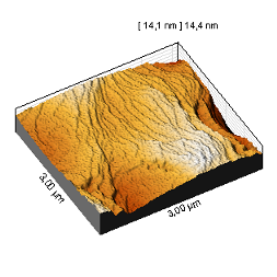
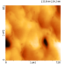
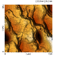
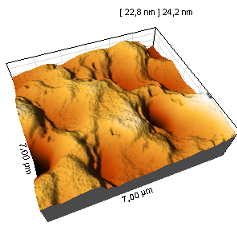
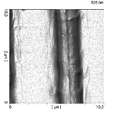
To make the surface structures more prominent it is often a good idea ( also for two-dimensional images) to introduce some kind of lighting effect. Here, you add or subtract the height change in a certain direction from the original image. The table below shows a comparison between images with and without "lighting" as well as the true 3D imaging; all images are structured and unstructured Gallium Nitride surfaces.
| Without "lighting" | With "lighting" | True 3D |
|---|---|---|
|  |
 |
 |  |
 |
 |  |
 |
The lighting effects may provide a stronger plastic view, also for two-dimensional imaging. often it is possible to observe significantly more details, and the images simply look more interesting.
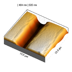
For the last, "stripe" structure, the imaging is still not ideal. You can see the details on the surface of the stripes, but it is not possible to see what it looks like in the groove between the stripes. In such cases it is often recommendable simply to switch off the color palette and only use lighting (or to change the colors of the color palette). Since this will cause the true height information to be lost, you can also switch to true 3D imaging.
In the last two images you can clearly see the surface structure inside the groove. Apart from the nice look, the disadvantage of the true 3D imaging is that it is no longer possible to measure the precise proportions, which is actually the purpose of AFM and other SPM measurements. Therefore, this imaging method should normally be avoided.